
What Equipment Can 750kva Cast Resin Dry Type Transformer Power?
For a typical 380V industrial power supply, the rated current of a 750kVA transformer is approximately 1145A (I = S / (√3 × U) = 750 / (1.732×0.38) ≈ 1145A).
For motor loads: It is recommended that the total power does not exceed 600kW (a 10% margin is safer for stable operation).
For pure resistive loads such as lighting/heating: It can power a maximum of 700~720kW.
Notes:
- Do Not Operate at Full Load for Long Periods: In actual use, it is advised to run at 80% load (i.e., 480kW) to avoid overheating and extend the transformer’s service life.
- Reactive Power Compensation: If the power factor is lower than 0.8, the actual usable power will be lower (e.g., cosφ=0.7 results in only 525kW). A capacitor compensation cabinet must be installed to improve the power factor.
750kva Cast Resin Dry Type Transformer technical Specifications
| Rated capacity | 750kva |
| Rated voltage | 6KV/10KV/33KV/35KV/40.5KV |
| model | SCB(10)-750/10/33/0.4KV or SCB(11)-750/10/33/0.4KV or SCB(12)-750/10/33/0.4KV or SCB(13)-750/10/33/0.4KV or SCB(14)-750/10/33/0.4KV or as per requirement |
| type | Dry type (cast resin) |
| No. of phase | 3 |
| Tapping range | ±2X2.5% |
| Vector Group | Dyn11/Yyn0/as per requirement |
| Winding material | Copper/Aluminum |
| Core material | GO Steel |
| Cooling method | AN/AF |
| standard | GB 1094/IEC 60076 |
| Winding Temperature Rise | F insulation class(105K) H insulation class(125K) |
| No load loss | 1520±15% W or as per requirement |
| Load loss | 6070±15% W or as per requirement |
| Short circuit impedance | 6% |
| shell | Cold-Rolled Steel Sheet(IP20/IP23)/Stainless Steel |
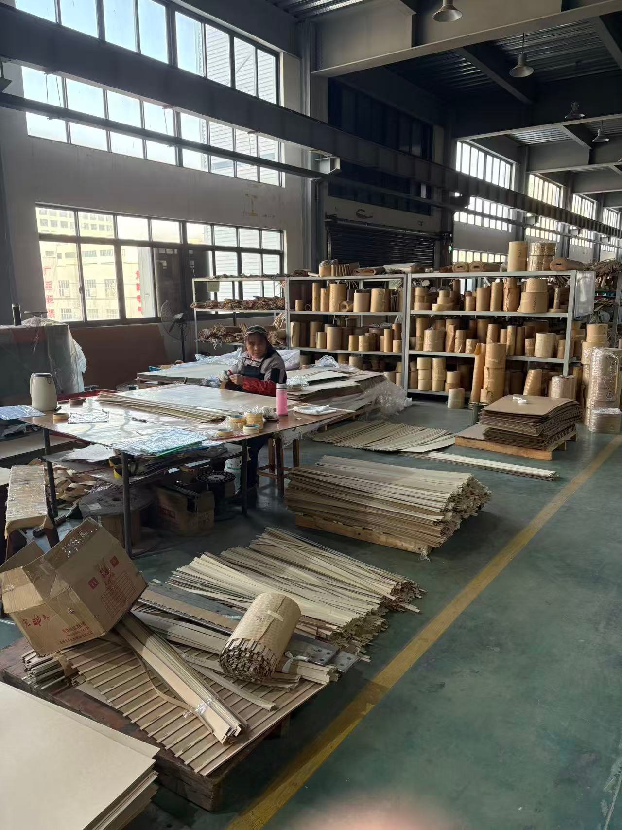
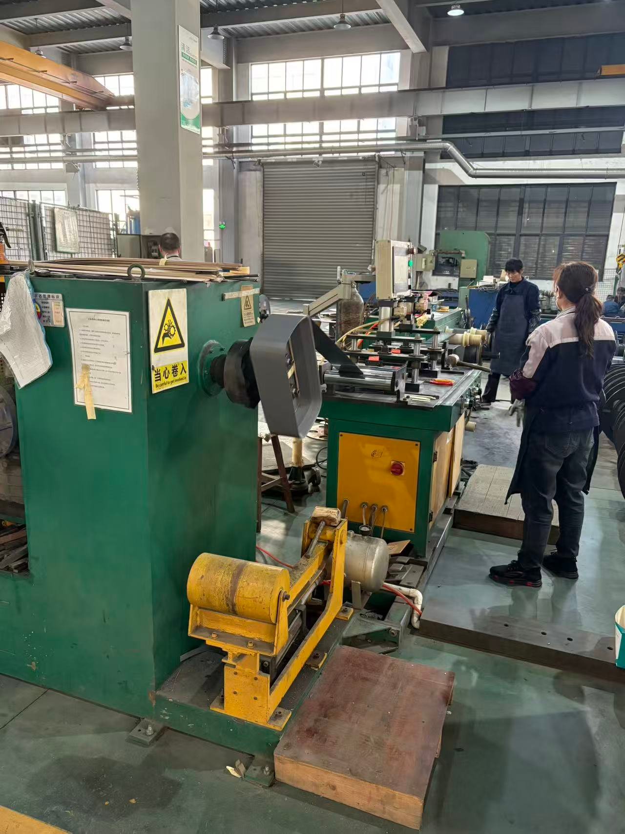
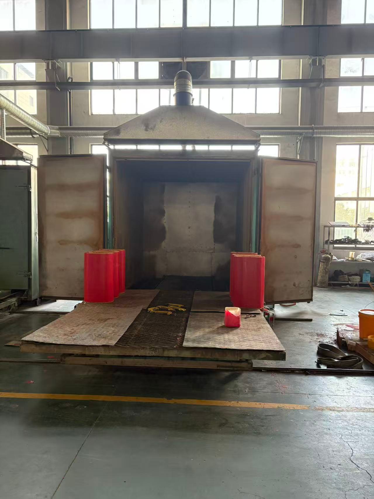
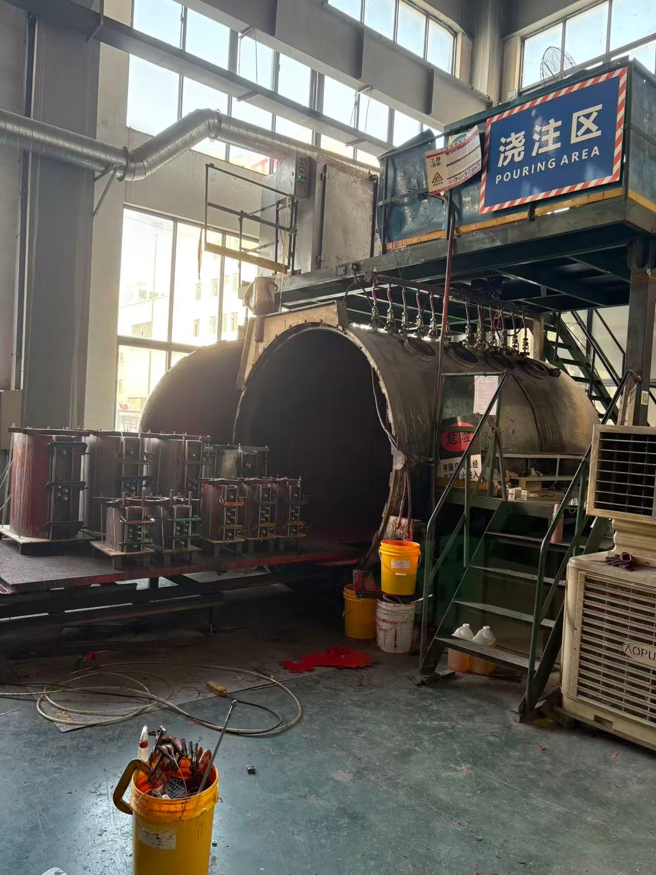
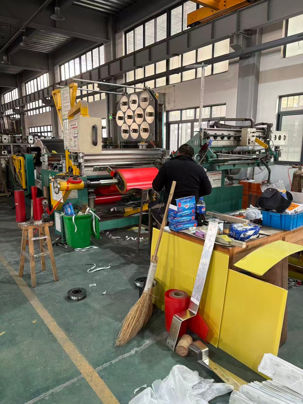
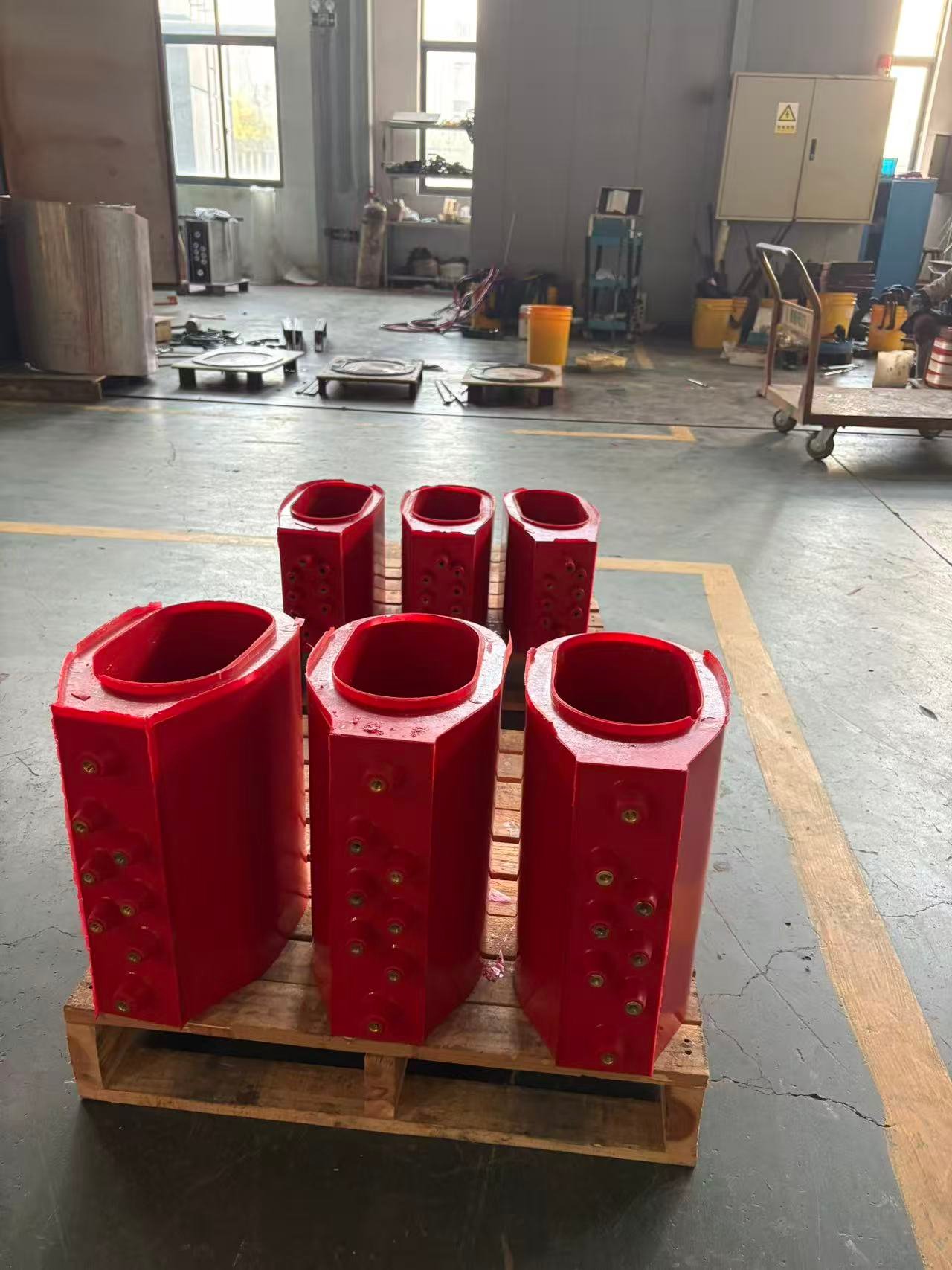
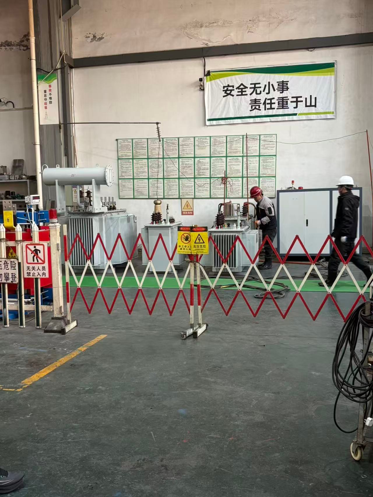
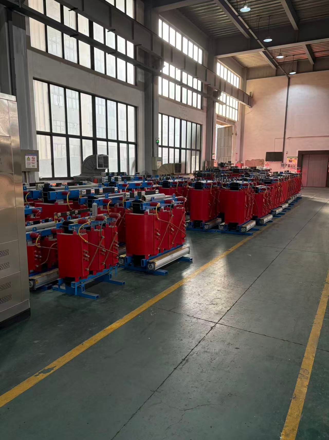
QIANLAI 750kva Cast Resin Dry Type Transformer Workshop