

Product overview
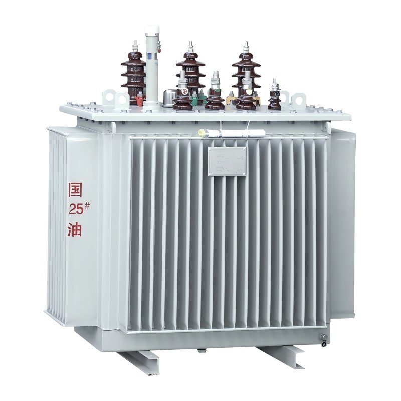
The 250 kVA oil immersed distribution transformer, featuring reliability, energy efficiency and easy maintenance, is ideal for medium and small-sized industrial and commercial applications as well as power distribution network upgrading needs.
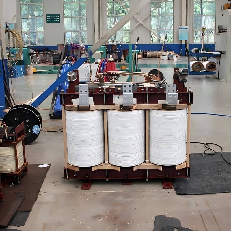
Designed specifically for medium-power distribution scenarios, the 250kVA oil immersed transformer adopts high-quality cold-rolled silicon steel sheets and winding made of copper/aluminum conductors with high-insulation oxidation treatment. It combines oil-immersed insulation with natural convection or forced air cooling systems to ensure long-term stable operation.
Compliant with a variety of voltage combinations and connection groups, it is widely used in factories, commercial complexes, residential communities, construction sites and power distribution station renovations.
Main technical Parameter
| Rated capacity | 250 KVA |
| Primary voltage | 33KV/35KV/13.2KV/11KV/10KV/6.3KV/6KV(customizable) |
| Tap changer | ±2*2.5/±5 |
| Secondary voltage | 400V/415V/433V/380V(customizable) |
| Vector group | Dyn11/Yzn11/Yyn0 |
| Number of phase | Three phase |
| frequency | 50hz |
| Temperature rise | 65K |
| Short circuit impedance | 4.0% |
| No load loss | Different series(S10,S11,S13,S14),got different loss data |
| Load loss 75ºC | Different series(S10,S11,S13,S14),got different loss data |
| Cooling type | ONAN |
| Oil type | 25#/45# |
| standards | IEC 60076-1 |
Standard Values of No-Load Current and Load Loss for 250kVA Three-Phase Oil-Immersed Transformers
The no-load current and load loss of 250kVA three phase oil immersed transformers (10kV/0.4kV, off-circuit tap changing) are mainly governed by GB/T 6451-2015 and GB 20052-2020. The standards vary with different energy efficiency classes and models. All load loss values are measured at 75℃.
Core Standard Parameter Table (10kV/0.4kV, Dyn11/Yyn0)
| Energy Efficiency/Model | No-Load Loss (Po) | Load Loss (Pk, at 75℃) | No-Load Current (I0) | Standard Basis |
| Energy Efficiency Class 3 (Minimum Allowable Value) | ≤290W | ≤3050W | ≤1.6% | GB 20052-2020 |
| Energy Efficiency Class 2 | ≤260W | ≤2440W | ≤1.4% | GB 20052-2020 |
| Energy Efficiency Class 1 | ≤230W | ≤2195W | ≤1.2% | GB 20052-2020 |
| Model S11 | 400W | 3150W | 1.6% | GB/T 6451-2015 |
| Model S13 | 290W | 3050W | 1.2% | Energy-Saving Design Value |
| Model S14 | 340W | 2440W | 1.0% | High-Efficiency Design Value |
Key Notes
- No-Load Currentis expressed as a percentage of the rated capacity, reflecting the magnetizing demand of the iron core. High-efficiency models (e.g., S13/S15) feature lower values thanks to the optimization of silicon steel sheets and structural design.
- Load Loss, also known as short-circuit loss at 75℃, corresponds to the copper loss of windings under rated current. It is directly related to the conductor cross-sectional area, material, and manufacturing processes.
- Allowable Deviation Range: A tolerance of ±15% is permitted for no-load loss and load loss, while a tolerance of ±30% applies to no-load current. All tests shall be conducted in accordance with GB/T 1094.1-2013.
- Special Scenarios: Structures such as amorphous alloy cores and wound cores can further reduce Po and I0. Specific values shall be subject to the manufacturer’s technical documents.