
What are the core components of a 11kv 415v 2000 kva Step Down Oil immersed type transformer?
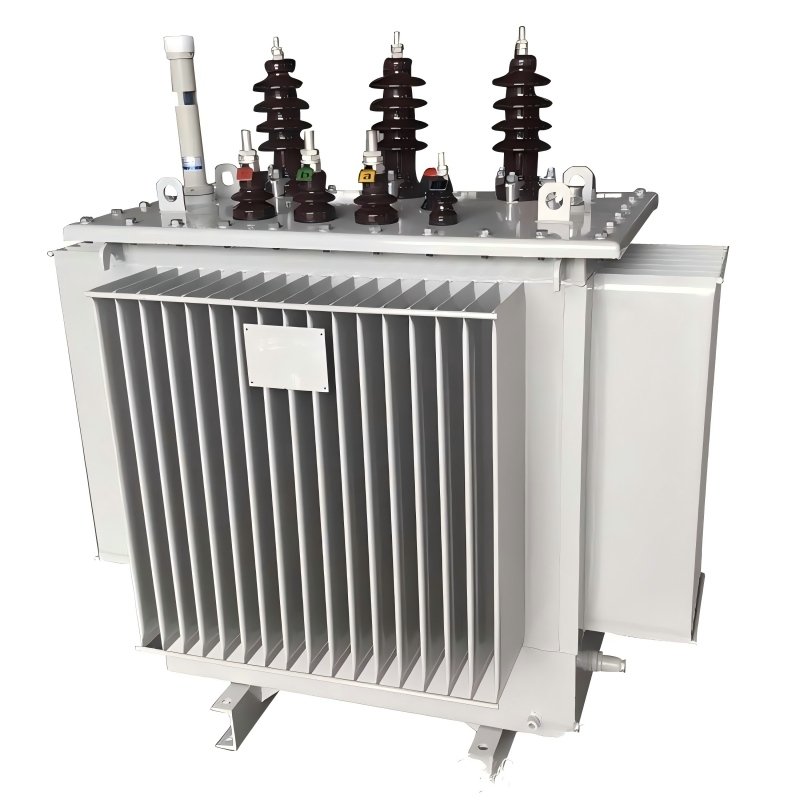
11kv 415v 2000 kva Step Down Oil immersed type transformer Main technical Parameter
| Rated capacity | 2000 KVA |
| Primary voltage | 33KV/35KV/13.2KV/11KV/10KV/6.3KV/6KV(customizable) |
| Tap changer | ±2*2.5/±5 |
| Secondary voltage | 400V/415V/433V/380V(customizable) |
| Vector group | Dyn11/Yzn11/Yyn0 |
| Number of phase | Three phase |
| frequency | 50hz |
| Temperature rise | 65K |
| Short circuit impedance | 4.0% |
| No load loss | S11:1940±15% Different series(S9,S11,S13,S14),got different loss data |
| Load loss 75ºC | S11:18300±15% Different series(S9,S11,S13,S14),got different loss data |
| Cooling type | ONAN |
| Oil type | 25#/45# |
| standards | IEC 60076-1 |
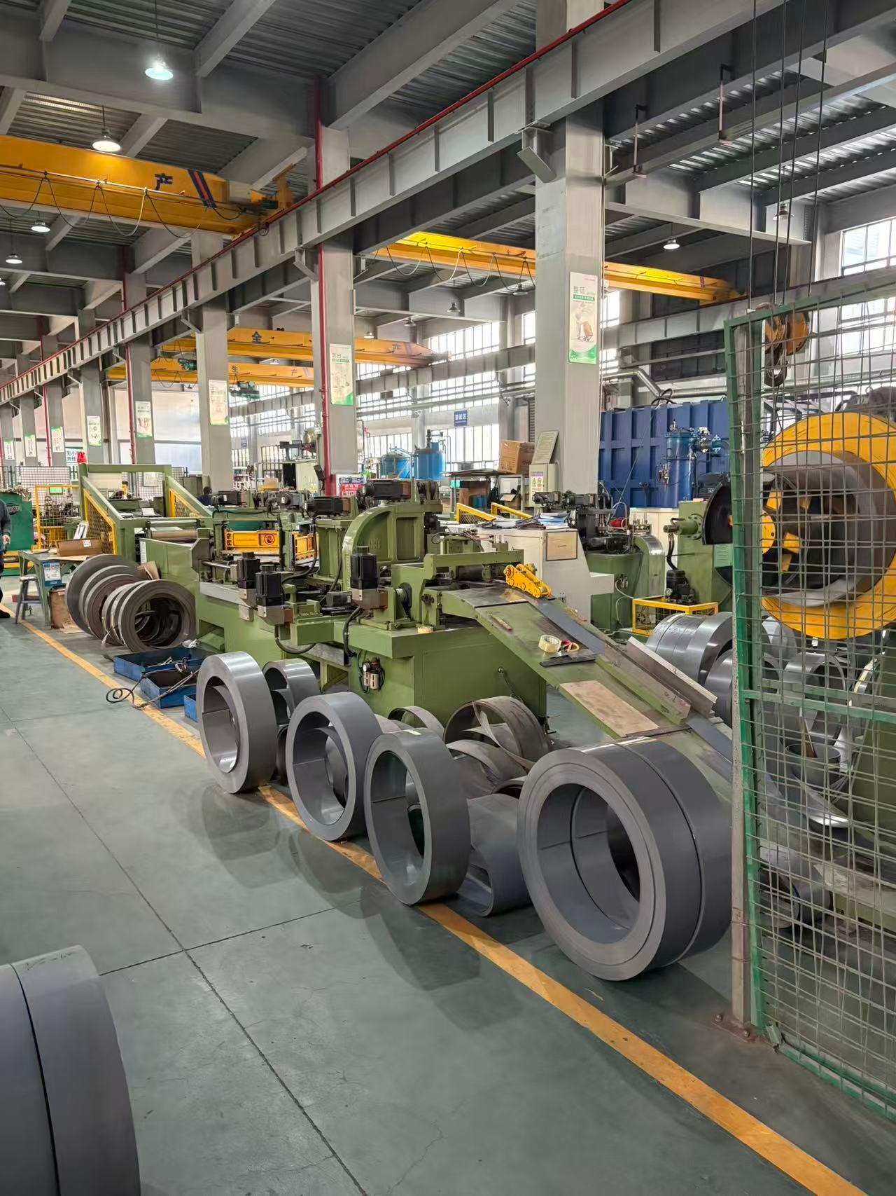
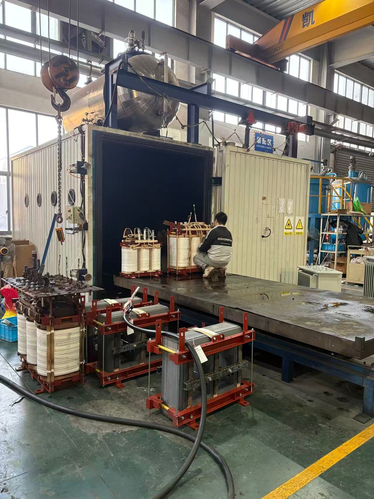
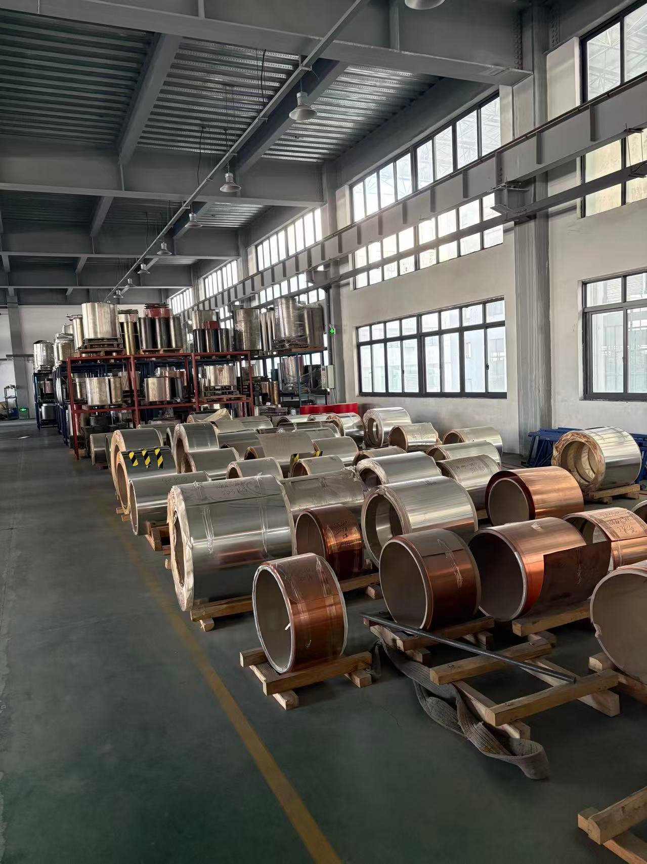
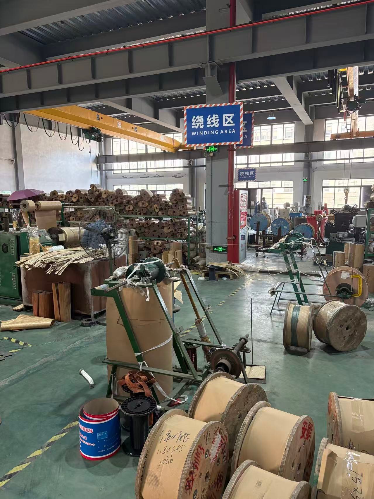
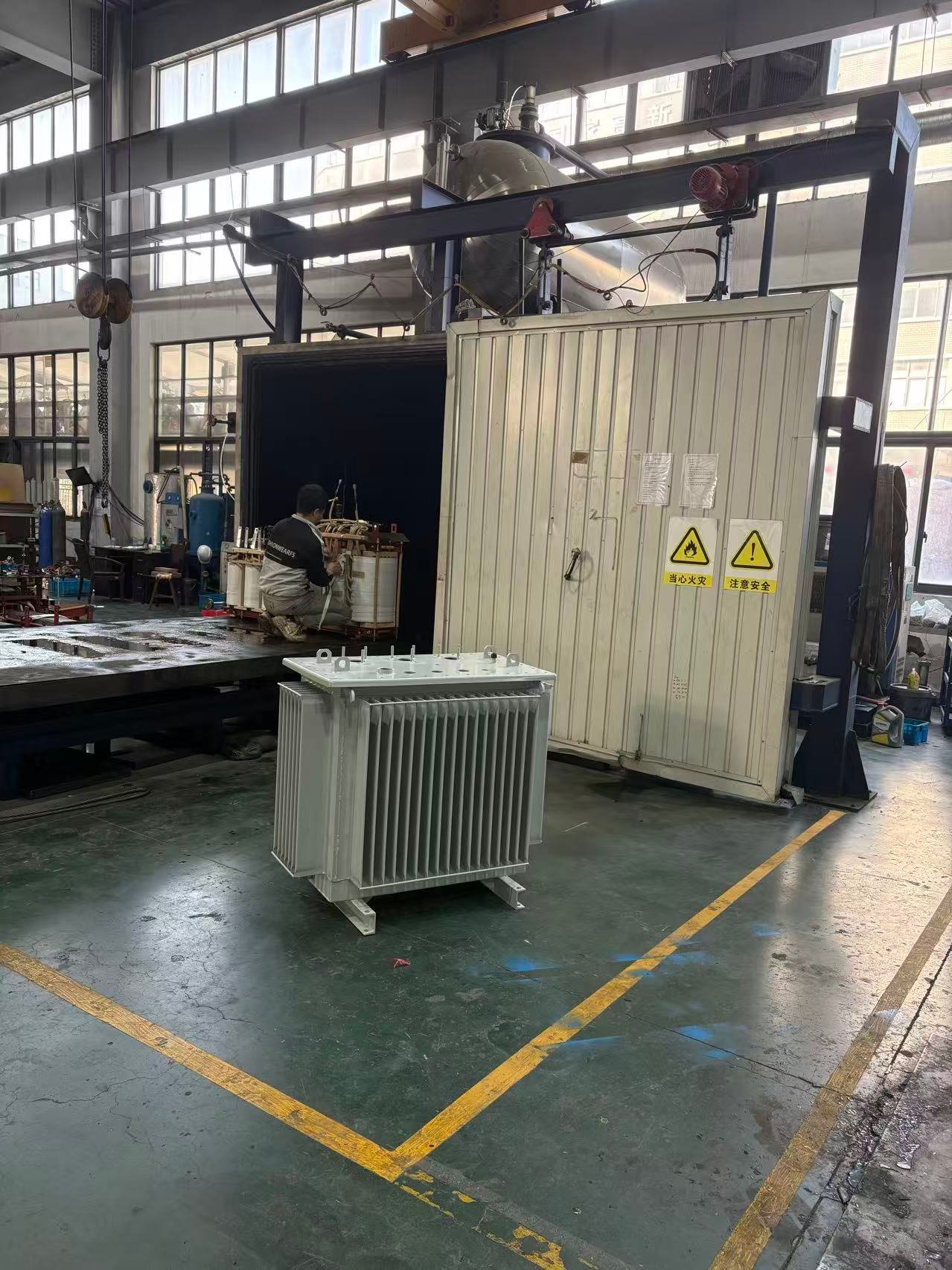
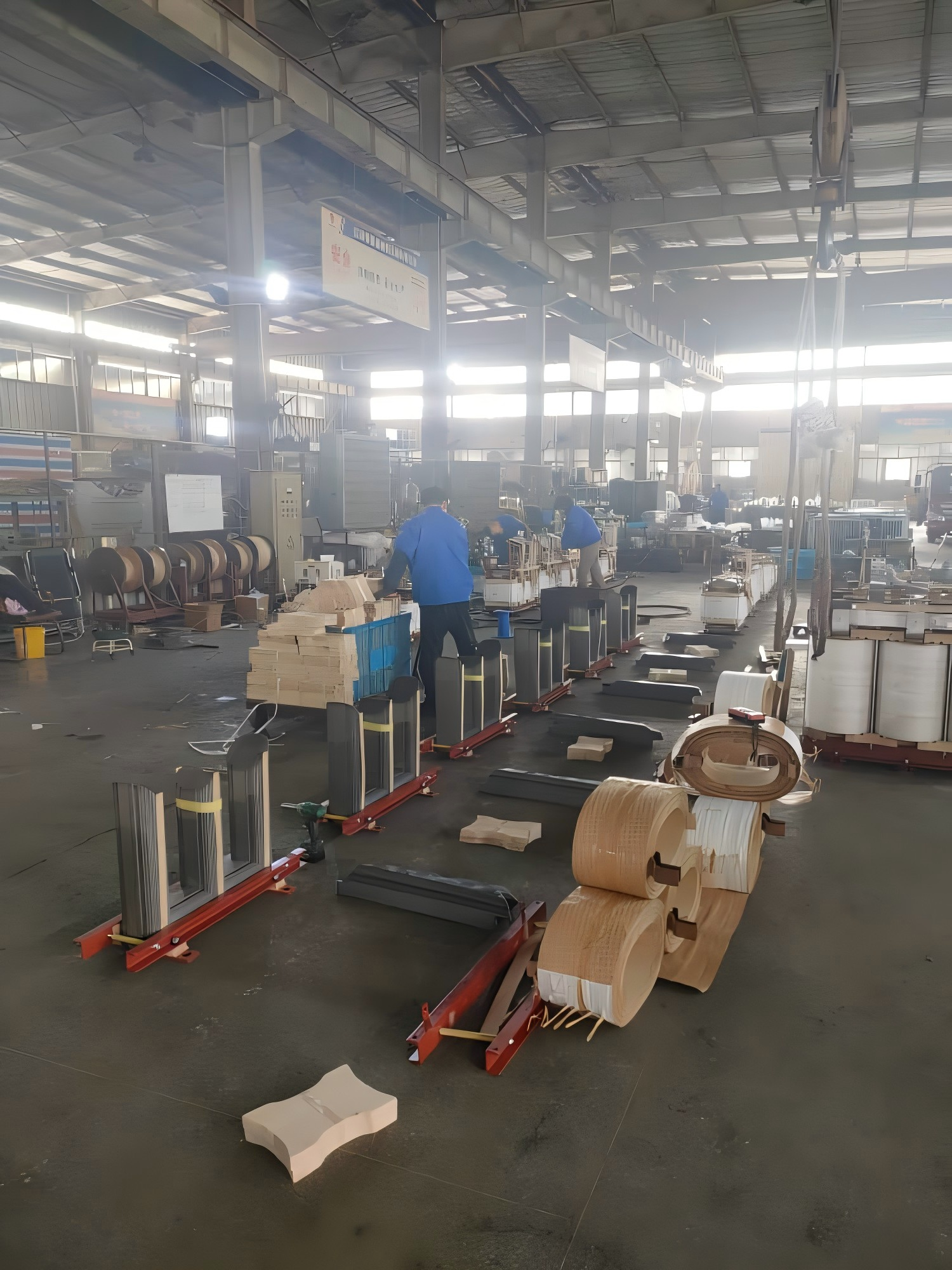
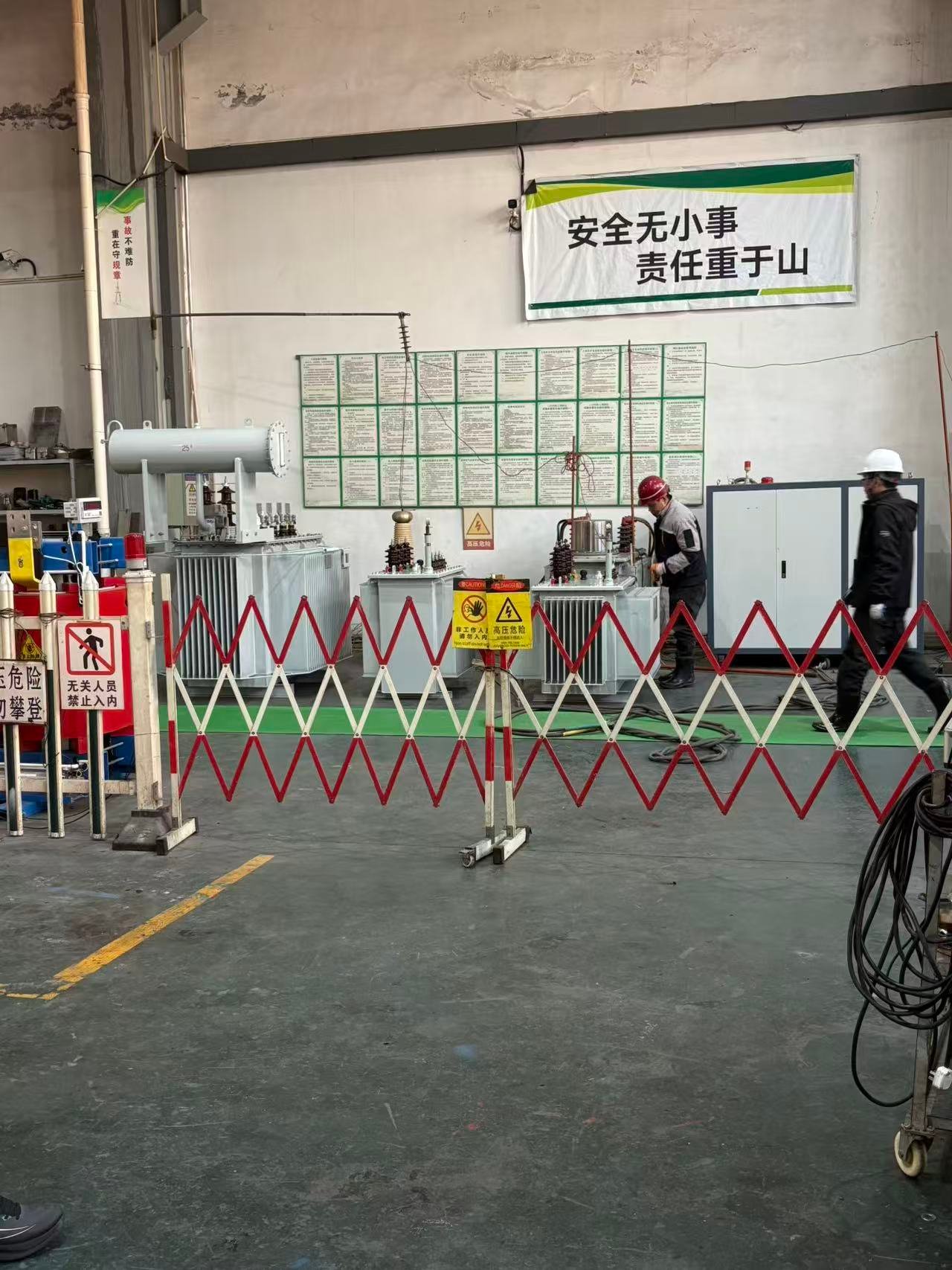
11kv 415v 2000 kva Step Down Oil immersed type transformer Production workshop