

Product overview
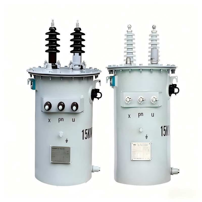
The 15 kVA pole mounted transformer is a single phase utility pole transformer designed for overhead power distribution networks.It is widely used in rural electrification projects, urban secondary distribution lines, and utility grid extensions.
As a professional transformer manufacturer with extensive export experience, QIANLAI supply 15 kVA pole mounted transformers that comply with IEC, IEEE, and ANSI standards, ensuring stable performance, high efficiency, and long service life under various climatic conditions.
Winding Connection Method of 15 kVA Pole Mounted Transformer
The internal windings of 15 kVA pole mounted transformer (mainly oil-immersed type) adopt a concentric winding structure. The connection method must match the distribution network voltage level (mainly 10 kV high-voltage side / 220 V low-voltage side), following the core principle of “coaxial arrangement of high and low-voltage windings with independent lead-out of head and tail ends”. The detailed specifications are as follows:
- Winding Layout and Electrical Connection Logic
Winding Hierarchical RelationshipThe low-voltage winding (fewer turns, thicker wire diameter) is directly wound on the insulating cylinder of the iron core column. The high-voltage winding (more turns, thinner wire diameter) is concentrically sleeved outside the low-voltage winding. Insulating spacers are installed between them, and oil ducts are reserved (for oil-immersed type), which not only ensure the insulation distance but also facilitate heat dissipation.
Winding Terminal Definition A single-phase transformer has only one set of high-voltage winding and one set of low-voltage winding. The industry universal terminal identification is as follows:
High-voltage winding: The head end is marked as H1, and the tail end is marked as H2
Low-voltage winding: The head end is marked as h1, and the tail end is marked as h2
- Mainstream Connection Methods (Adapted to Distribution Scenarios)
- Standard Step-Down Connection (Most Commonly Used for 10 kV/220 V)
Connection Form: The high-voltage winding terminals H1 and H2 are connected to the 10 kV single-phase power grid, and the low-voltage winding terminals h1 and h2 lead out 220 V voltage for load supply.
Polarity Requirement: Subtractive polarity connection is adopted (industry default standard). That is, when current flows in from H1 and out from h1, the magnetic flux generated by the high and low-voltage windings is in the same direction, ensuring voltage phase matching and avoiding voltage cancellation.
Practical Key Points: The lead wires of the high and low-voltage windings must be fixed with insulating brackets. The insulation distance between the leads and the iron core/tank must be ≥ 30 mm (for 10 kV class). The lead joints shall be tinned to reduce contact resistance.
- Tap Changer Connection (Optional, Adapted to Voltage Fine-Tuning)
The high-voltage winding of some 15 kVA transformers is equipped with tapping taps to adjust the output voltage and cope with grid voltage fluctuations:
2–3 tapping terminals (usually ±5% voltage regulation gears) are set on the high-voltage winding near the H2 end, marked as H0 (main tap), H3 (+5%), H4 (-5%)
During wiring, select the tapping terminal according to the grid voltage: connect to the -5% gear when the grid voltage is high, and connect to the +5% gear when the grid voltage is low, to ensure that the output voltage of the low-voltage side is stable within the range of 220 V ± 5%.
- Parallel Operation Connection (Multi-Unit Combination for Capacity Expansion)
If it is necessary to increase the power supply capacity, multiple 15 kVA single-phase transformers can be operated in parallel, which must meet 3 core conditions:
The same voltage ratio;
The same connection group (all single-phase transformers are I/I-12);
The short-circuit impedance deviation ≤ 10%.
Wiring Method: The H1 and H2 terminals of multiple transformers are respectively connected in parallel to the high-voltage power grid, and the h1 and h2 terminals are respectively connected in parallel before connecting to the load.
III. Wiring Differences of Dry-Type Single-Phase Transformers
The winding connection logic of dry-type 15 kVA pole mounted single phase transformers is consistent with that of oil-immersed transformers. The core differences are as follows:
The windings have no oil duct design, and insulation depends on epoxy resin casting layer or Nomex paper;
The lead-out wires adopt silicone rubber insulated bushings, without considering oil-immersed sealing, and the installation is simpler.
- Key Precautions
Before wiring, use a megohmmeter to test the winding insulation resistance. For the 10 kV class, the insulation resistance of the high-voltage winding to ground shall be ≥ 300 MΩ, and that of the low-voltage winding to ground shall be ≥ 50 MΩ. Wiring can be carried out only after passing the test.
Fuses or circuit breakers shall be installed on the low-voltage side to prevent transformer damage caused by load short circuit.
The transformer shell must be reliably grounded, and the grounding resistance shall be ≤ 4 Ω to avoid electric leakage hazards.
Main technical Parameter
| Rated capacity | 15KVA |
| Primary voltage | 7.62KV/6.35KV/11KV/13.2KV/13.8KV/34.5KV(customizable) |
| Secondary voltage | 480V/415V/433V/380V/277V/240V(customizable) |
| Number of phase | Single phase |
| frequency | 50/60hz |
| Temperature rise | 65K |
| Core type | CRGO or Amorphous |
| No load loss | 50W(CRGO),(customizable) |
| Load loss | 195W(CRGO),(customizable) |
| Cooling type | ONAN |
| Oil type | Mineral Oil / FR3 (optional) |
| standards | IEEE Std C57/IEC 60076-1 |


")