
100 kva pole mounted transformer/QIANLAI ELECTRIC-Reliable pole mounted transformer suppliers
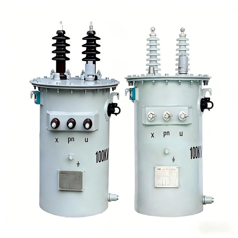
The 100 kVA pole mounted transformer is a single phase pole transformer designed for overhead power distribution networks.It is widely used in rural electrification projects, urban secondary distribution lines, and utility grid extensions.
As a professional transformer manufacturer with extensive export experience, we supply 100 kVA pole mounted transformers that comply with IEC, IEEE, and ANSI standards, ensuring stable performance, high efficiency, and long service life under various climatic conditions.
General Production Process of 100 kva pole mounted transformer
Stage 1: Design and Raw Material Preparation
Technical Design: Determine transformer specifications (capacity, voltage class, impedance, losses, etc.) based on customer or national standards (e.g., GB, IEC, ANSI). Complete electromagnetic calculations, structural design, and drawing preparation.
Raw Material Inspection:
Electrical Steel (Laminations):
Check permeability, specific core loss (e.g., B30G130), thickness, and quality of the surface insulation coating.
Magnet Wire: Check conductor resistance, insulation layer (enamel) thickness, voltage withstand, and thermal class (e.g., Class 155 polyester enameled wire).
Insulation Materials: Check electrical strength, thermal class, and dimensions of insulation pressboard (for turns, layers, spacers), insulating oil (or synthetic ester), adhesive tapes, etc.
Steel Materials: Material and dimensions for structural parts like the tank, clamping frames, and radiators.
Stage 2: Core Manufacturing
Slitting and Cutting: The silicon steel coil is first slit to the required width via a slitting line, then precisely cut into specific shapes (e.g., E, C, or stepped laminations) using a high-precision cut-to-length line (or guillotine/shear line) to optimize the magnetic path and reduce losses and noise.
Stacking and Clamping:
The cut laminations are stacked alternately onto the core legs and yokes according to design drawings to minimize joint gaps and no-load loss.
The core is clamped into a solid unit using frames, insulated bolts, and straps to ensure mechanical strength. Core clamping frames must be reliably grounded.
Core Testing: Check stacking dimensions, clamping force, and perform preliminary no-load loss tests (if equipment permits).
Stage 3: Coil Winding and Pre-assembly
Coil Winding:
Low Voltage (LV) Coil: Typically wound on an automatic winding machine, magnet wire is wound onto an insulating cylinder with interlayer insulation paper and spacers to form oil ducts. Winding must be tight and uniform.
High Voltage (HV) Coil: Wound using layer or sectional winding methods, with strict control over turn-to-turn and layer insulation. Tap lead positions must be precise.
Coil Processing:
After winding, coils undergo constant-pressure drying to remove moisture.
Impregnation with insulating varnish or resin (e.g., epoxy) and curing treatment are performed to enhance the coil’s mechanical strength, moisture resistance, and electrical strength.
Coil Testing: Use turn-to-turn testers and DC resistance testers to check for interturn shorts and resistance balance.
Stage 4: Active Part Assembly
This is the core stage of transformer manufacturing.
Insulation Assembly: The LV coil and HV coil are successively placed over the core leg(s). Insulation pressboards and spacers form the main insulation and oil ducts between coils.
Lead Preparation and Connection: Coil leads (taps) are connected to the tap changer and bushing terminals using copper bars or cables. All connections must be securely welded or crimped and properly insulated with wrapping.
Pressing and Securing: Appropriate clamping pressure is applied to the coils using pressure plates, bolts, etc., to prevent loosening and noise caused by electromagnetic forces during operation.
Pre-drying: The assembled active part is placed in a vacuum drying oven for thorough removal of moisture from the insulating materials under high temperature (e.g., 110-130°C) and high vacuum.
Stage 5: Tank and Accessory Processing
TankFabrication: Steel plates are cut, bent, and welded to form the tank body and radiators (or corrugated panels). Requirements include good sealing and no leaks.
Surface Treatment: The inner and outer surfaces of the tank undergo shot blasting, rust removal, cleaning, and then spraying with anti-corrosion primer and topcoat.
Accessory Preparation: Prepare HV/LV bushings, pressure relief device, oil level gauge, temperature indicator, tap changer (if any), etc., ensuring their performance is qualified.
Stage 6: Final Assembly and Oil Filling
Active Part Placement: The dried active part is lifted into the clean and dry tank and securely fixed.
Accessory Installation: Install all bushings, switches, valves, gauges, and other accessories.
Vacuum Oil Filling:
The tank is evacuated to a high vacuum (e.g., <133 Pa) to remove air and trace moisture from the active part and tank interior.
Under vacuum, qualified transformer oil (or environmentally friendly fluid) that has been strictly filtered, degassed, and dehydrated is injected into the tank.
After filling, the vacuum is maintained for a period before being released, and the oil level is adjusted.
Stage 7: Routine Tests and Packaging
Conduct full routine tests according to national standards (e.g., GB/T 6451) to ensure each unit is qualified:
Routine Tests:
Winding Resistance Measurement
Voltage Ratio and Vector Group Verification
Insulation Resistance and Absorption Ratio/Polarization Index Measurement
No-Load Loss and No-Load Current Measurement
Load Loss and Short-Circuit Impedance Measurement
Power Frequency Withstand Voltage Test (HV/LV windings to earth and between windings)
Induced Voltage Withstand Test (to test interturn and interlayer insulation)
Final Inspection and Packaging: Clean the exterior, attach the nameplate, complete technical documentation, and package for shock and moisture protection.
Key Quality Control Points
Core loss and stacking quality
Coil winding accuracy and insulation processing
Dryness of the active part (moisture content)
Purity of the insulating oil (or fluid)
Results of all high-voltage tests
Tank sealing integrity
Main technical Parameter
| Rated capacity | 100KVA |
| Primary voltage | 7.62KV/6.35KV/11KV/13.2KV/13.8KV/34.5KV(customizable) |
| Secondary voltage | 480V/415V/433V/380V/277V/240V(customizable) |
| Number of phase | Single phase |
| frequency | 50/60hz |
| Temperature rise | 65K |
| Core type | CRGO or Amorphous |
| No load loss | 210W(CRGO),(customizable) |
| Load loss | 850W(CRGO),(customizable) |
| Cooling type | ONAN |
| Oil type | Mineral Oil / FR3 (optional) |
| standards | IEEE Std C57/IEC 60076-1 |