

Product overview
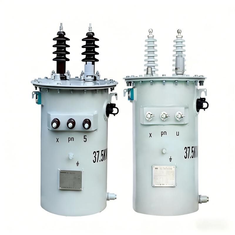
The 37.5 kVA pole mounted transformer is a single phase utility pole transformer designed for overhead power distribution networks.It is widely used in rural electrification projects, urban secondary distribution lines, and utility grid extensions.
As a professional transformer manufacturer with extensive export experience, QIANLAI supply 37.5 kVA pole mounted transformers that comply with IEC, IEEE, and ANSI standards, ensuring stable performance, high efficiency, and long service life under various climatic conditions.
Manufacturing & testing Process of 37.5KVA pole mounted transformer
The manufacturing process of polemounted transformers is designed around three core objectives: high reliability, outdoor weather resistance, and low loss. The overall process is divided into three stages: core component processing, final assembly and commissioning, and inspection before delivery, with each link strictly complying with power equipment manufacturing standards (such as the GB 1094 series). The detailed process breakdown is as follows:
- Core Component Processing Stage
This is a key link that determines transformer performance, mainly including the production of iron cores and windings.
Iron Core Processing Technology
Material Cutting and LaminationOriented silicon steel sheets or amorphous alloy strips are precisely cut using a CNC shearing line, with the dimensional tolerance of sheets controlled within ≤±0.1mm. The surface insulation coating of silicon steel sheets must be repaired to avoid damage during shearing.Lamination methods are divided into staggered lamination (for core-type structures) and butt lamination (for shell-type structures). The stacking factor should be ≥0.97, and special fixtures are used for compression to prevent core vibration and noise during operation.
Annealing and CuringAfter lamination, silicon steel cores undergo low-temperature annealing treatment (750–800℃) to eliminate shearing stress and restore the magnetic properties of silicon steel sheets; amorphous alloy cores are annealed in a vacuum environment to prevent oxidation. After annealing, epoxy resin adhesive is used for bonding and curing to form an integral rigid structure, enhancing vibration resistance.
Iron Core Grounding TreatmentThe iron core must be reliably grounded at a single point. The grounding strip is made of oxygen-free copper, and the welding joint is protected by insulation to avoid eddy current loss and local overheating caused by multi-point grounding.
Winding Processing Technology
Conductor Selection and WindingHigh-voltage windings use polyurethane enameled round copper wires, while low-voltage windings use cable paper-covered flat copper wires or copper foils; for aluminum windings, high-purity electrical aluminum wires are selected.Layer-by-layer winding is performed using a CNC winding machine, with strict control over the radial and axial dimensions of the windings. Dot adhesive insulation paper is placed between layers, and the winding tension is uniform to prevent conductor stretching and deformation.Winding arrangement follows the low-voltage to high-voltage structure (for core-type) or low-voltage to high-voltage to low-voltage structure (for shell-type). A main insulation gap is reserved between high and low voltage windings, and insulation support strips are placed to ensure smooth oil ducts.
Winding Drying and CuringThe wound windings undergo vacuum drying treatment (vacuum degree ≤50Pa, temperature 105–110℃) to remove moisture from insulation materials; after drying, epoxy resin adhesive is injected and heated for curing again, forming a solid integral structure of the windings to improve insulation performance and short-circuit resistance.
Winding Lead ProcessingWinding leads are connected using cold-pressed terminals, the joints are tinned, and insulated heat-shrinkable tubes are wrapped externally to ensure reliable electrical connection and compliance with insulation strength requirements.
- Final Assembly and Commissioning Stage
Integrating core components with oil tanks, bushings, protection devices, etc., is a critical step to ensure safe outdoor operation.
Core Assembly
The cured iron core is hoisted into the windings, and the concentricity is calibrated (deviation ≤2mm). The tap changer (if equipped) is installed, with its contacts kept clean and free of oxidation, and gear switching should be flexible.
Before the overall hoisting of the core, secondary vacuum drying is required to ensure that the moisture content of the core is ≤0.5%, avoiding insulation dampening during operation.
Oil Tank Assembly and Oil Filling
Oil Tank Fabrication: Using 2–3mm cold-rolled steel plates, the tank is formed by CNC bending and welding. Welded joints are tested via kerosene leakage test, and are qualified if no leakage is detected. The internal and external surfaces of the tank are subjected to double anti-corrosion treatment of electrostatic spraying + hot-dip galvanizing, with the coating thickness ≥80μm and salt spray corrosion resistance ≥1000h.
Sealing Treatment: The tank cover and body are sealed with nitrile rubber sealing rings, fastened with hoop clamps or compression nails to ensure a fully sealed structure; corrugated fin radiators or plate-type radiators are welded to the tank wall, with an air gap reserved to adapt to oil volume changes.
Vacuum Oil Filling: After the core is hoisted into the tank, vacuum is drawn to ≤50Pa, and qualified transformer oil (generally #25 or #45 transformer oil) is injected. Vacuum pumping is maintained during the oil filling process to avoid air bubbles mixing into the oil. After filling, the transformer is left to stand for 24h to remove air inside the core.
Accessory Installation
Outdoor Bushing Installation: High-voltage bushings are porcelain or epoxy resin bushings, and low-voltage bushings are installed for side lead-out. After connecting the bushings to the winding leads, insulation wrapping is applied; the surface of the bushings is treated for anti-pollution flashover, with a creepage distance ratio ≥20mm/kV.
Protection Device Installation: Drop-out fuses and surge arresters are installed on the high-voltage side, and circuit breakers are installed on the low-voltage side; accessories such as oil level gauges, temperature controllers, and anti-theft locks are installed as required, with reliable sealing at accessory interfaces.
III. Inspection and Delivery Stage
All transformers must pass comprehensive performance testing before leaving the factory, covering electrical performance, mechanical performance, and weather resistance.
Electrical Performance Testing
No-Load Test: Measures no-load loss and no-load current to verify core magnetic properties; the loss value must be lower than the requirements of national standards.
Load Test: Measures load loss and short-circuit impedance to inspect winding resistance and temperature rise characteristics.
Withstand Voltage Test: Includes applied voltage withstand test (applying 1.5 times the rated voltage for 1min) and induced voltage withstand test (applying 2 times the rated voltage for 1min), which are qualified if no breakdown or flashover occurs.
Insulation Resistance Test: Uses a megohmmeter to measure the insulation resistance between windings and ground, and between high and low voltage windings; the resistance value should be ≥1000MΩ at room temperature.
Mechanical and Weather Resistance Testing
Sealing Test: The oil tank is filled with compressed air at 0.03MPa and immersed in water for 2h; it is qualified if no air bubbles escape.
Vibration and Noise Test: During no-load operation, the noise level should be ≤55dB (measured 1m away from the equipment).
Salt Spray Corrosion Test: Sampled products undergo a 1000h salt spray test, with no coating peeling or rusting allowed.
Pre-Delivery Finishing
Clean the transformer surface, affix the nameplate (marking model, capacity, voltage, impedance and other parameters) and safety warning signs;
Attach factory inspection reports, product manuals and certificates of conformity, package the transformer in rainproof and moisture-proof wooden cases, and ensure secure fixing for transportation.
Main technical Parameter
| Rated capacity | 37.5KVA |
| Primary voltage | 7.62KV/6.35KV/11KV/13.2KV/13.8KV/34.5KV(customizable) |
| Secondary voltage | 480V/415V/433V/380V/277V/240V(customizable) |
| Number of phase | Single phase |
| frequency | 50/60hz |
| Temperature rise | 65K |
| Core type | CRGO or Amorphous |
| No load loss | 105W(CRGO),(customizable) |
| Load loss | 360W(CRGO),(customizable) |
| Cooling type | ONAN |
| Oil type | Mineral Oil / FR3 (optional) |
| standards | IEEE Std C57/IEC 60076-1 |